From Wi-Fi to Li-Fi, sending data via light using Arduino and JavaScript
13/02/2023There’s a big chance you’re reading this post on a device connected to the internet via Wi-Fi. Your router broadcasts data that is received by a small antenna in your computer, phone or tablet. This data is transmitted over radio waves at a frequency of either 2.4GHz or 5GHz. However, other parts of the electromagnetic spectrum can be used to transmit information. Using visible light, data can be encoded and transmitted using a technology called Li-Fi which aims at using your existing lights for wireless communication.
In this post, I’ll explain how it works by building a prototype of a Li-Fi project using JavaScript and Arduino.
If you prefer tutorials in video formats, you can check out this video on Youtube.
Demo
First, here’s the final outcome of my experiments. Data is transmitted using visible light between two devices. This demo shows how a Stripe Payment Link can be sent but this technology also works to transmit audio files, videos, and more.

Material
There are a lot of different ways to build this. Here’s the list of components I used for my prototype:
- 2 Arduino UNO
- A breadboard
- Jumper wires
- A 10k resistor
- A Neopixel Jewel (a standard LED will work too but you will need an extra resistor and the transmitter and receiver will have to be set up much closer as an LED is less bright than the Jewel).
- A phototransistor
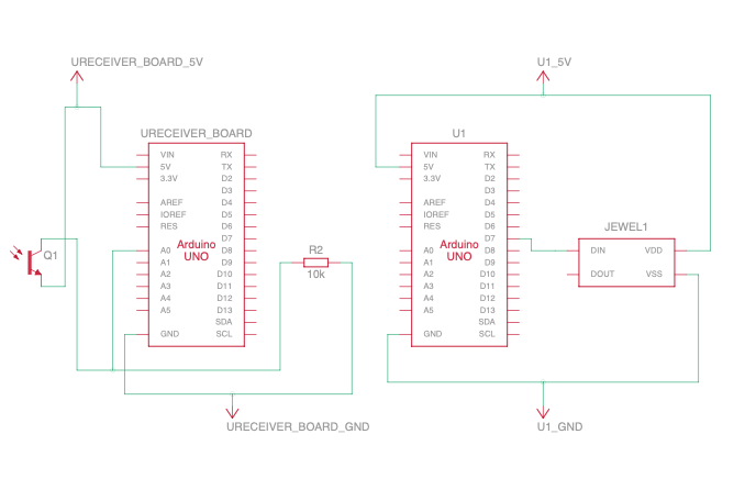
They are then assembled following these schematics:

The board shown at the top is used as the transmitter and will use the Neopixel Jewel connected to pin 7 of the Arduino to send data via light. The board below is the receiver and uses the phototransistor connected to pin A0 to convert the light intensity back into data.
Now, let’s dive deeper into how it works.
Deep dive
Converting data
If you’re used to working with computers, you have probably heard many times that, at the lowest level, computers deal with data as a bunch of 1s and 0s. Using light as a medium to send information is quite convenient, as the only state a light can be in is either “on” or “off”. As a result, for this experiment, we’re going to encode 1 as the “on” state and 0 as the “off” one.
For the rest of this post, let’s consider that we want to transmit the string “Hello, world”.
Strings are made of characters, and a single character is 1 byte of data. As a byte is 8 bits, each letter in this string can be converted to 8 bits.
 The decimal representation of the ASCII letter “H” is the integer 72, which can be converted to binary as 01001000.
The complete string “Hello, world” represented in binary is the following:
01001000 01100101 01101100 01101100 01101111 00101100 00100000 01110111 01101111 01110010 01101100 01100100
To do this conversion using JavaScript, you can use the built-in methods charCodeAt, toString and padStart.
// This function takes in a string to convert
const convertToBinary = (string) => {
   // The string is split into an array of characters
   return string.split('').map(function (char) {
       // For each character, charCodeAt(0) is called to get its decimal representation, followed by .toString(2) to get its binary representation and .padStart(8, ‘0’) to make sure the leading 0s are kept and each byte has 8 digits.
       return char.charCodeAt(0).toString(2).padStart(8, '0');
     // Finally, join all converted characters together into a single string.
   }).join(' ');
}
Now that I’ve covered how the data is converted, let’s talk about how it is transmitted.
Transmitting the data
As mentioned above, a string can be converted to binary. The 1s can be associated with the “on” state of a light, and the 0s with the “off”. At first, you might think that a solution would be to loop through the whole binary code, turning the light on when the bit is equal to 1 and turning it off when the bit is 0. A receiver set up as a light sensor could then decode the messages by turning the light states back to 1s and 0s.
While this is how it works at its core, this is where the details get really interesting.
Because it’s important that both the transmitter and receiver stay in sync, we need to create a custom communication protocol.
First, why do they need to stay in sync? I mentioned in the previous part of this post that the binary equivalent of “Hello, world” is
01001000 01100101 01101100 01101100 01101111 00101100 00100000 01110111 01101111 01110010 01101100 01100100
If the receiver starts decoding the data at the first bit, then it will be able to retrieve the right information; however that might not always be the case. If the receiver is out of sync by even a single bit, the information it will decode will be incorrect.
For example, if instead of the first 8 bits “01001000”, it gets “10010000”, it will decode “�” instead of “H” as this value is not a valid ASCII character, and all subsequent characters will also be wrongly decoded.
Besides, as this technology aims at being used as part of the lights people already have set up in their homes or offices, the lights will likely already be on by the time they’re also used to transmit information.
As a result, when the lights are on but not transmitting information, the receiver will read an input equal to “111111111111…”, so a communication protocol is needed to define when a message is starting to be sent so the receiver can start the decoding process.
Setting up a communication protocol
A light might be on simply to illuminate a space, not to transmit information, so there needs to be some kind of preamble to indicate to the receiver that a message is about to be transmitted. This preamble will be a change from “on” to “off” state.
Also, we need to pick a unit of time to define how long the light should reflect the value of each bit transferred. First, let’s say that each bit changes the state of the light for 100 milliseconds, so when the bit is equal to 1, the light stays on for 100 milliseconds, and if the bit is 0, the light turns off for 100 milliseconds.
Finally, when the 8 bits have been transferred, the light will be brought back to its original “on” state.
It can be graphically represented like this:

Then, on the receiver side (represented as the second row of intervals below), we need to detect the preamble when the light changes state from “on” to “off”. Then, we need to wait 1.5x the interval as we don’t want to sample the preamble but we want to make sure we sample our data within the next 100ms where data starts to be transmitted, and sample it 8 times to get the value of each bit.

Implementation
I decided to use the Johnny-Five JavaScript framework for this. After installing it , I started by declaring a few variables and instantiating the transmitter board.
// Import the required packages
const five = require("johnny-five");
const pixel = require("node-pixel");
// Instantiate a new board using the first Arduino’s port
var board = new five.Board({ port: "/dev/cu.usbmodem11101" });
// Declare variables to store the pin number that the light sensor is connected to, the value of the interval and the string to transmit.
const LED_PIN = 9;
const INTERVAL = 100;
const string = "Hello, world";
const strLength = string.length;
Then, when the board is ready to receive instructions, I instantiate the Neopixel strip with the pin it is connected to on the Arduino as well as the number of LEDs, turn the light on and call my sendBytes function.
board.on("ready", async function () {
   const strip = new pixel.Strip({
       board: this,
       controller: "FIRMATA",
       strips: [{ pin: 7, length: 7 },],
       gamma: 2.8,
   });
   strip.on("ready", function () {
       strip.color('#fff');
       strip.show();
   });
   await delay(3000);
   sendBytes(strip);
});
This function implements the communication protocol defined in the previous section.
const sendBytes = async (strip) => {
   for (var i = 0; i < strLength; i++) {
       strip.off();
       strip.show();
       await delay(INTERVAL);

       const bits = convertToBinary(string[i]);

       for (var y = 0; y < 8; y++) {
           const ledState = bits[y];

           if (ledState === '1') {
               strip.color('#fff');
               strip.show();
           } else {
               strip.off();
               strip.show();
           }
           await delay(INTERVAL);
       }

       strip.color('#fff');
       strip.show();
       await delay(INTERVAL);
   }
   await delay(INTERVAL);
   sendBytes(strip);
}
For each letter in the string transmitted, it goes through the following steps:
- Start by turning the light off
- Apply a delay of 100ms
- Convert the letter into binary
- Loop through each bit
- If its value is 1, turn the light on and if it is 0, turn it off
- Apply the delay of 100ms
- When it has gone through the 8 bits, turn the light back on and apply the delay again
- Once all letters are sent, call sendBytes recursively to continuously send the data.
The delay function is simply a setTimeout function inside a Promise.
const delay = (ms) => {
   return new Promise(resolve => {
       setTimeout(resolve, ms);
   });
}
Before running this code, you need to install the right firmware onto the board. To do this, you can follow the instructions on the node-pixel repository.
Then, it should result in the light flashing like this:

Now that the transmitter is able to change the state of the light depending on the bits sent, let’s set up the receiver side.
Decoding the data
To set up the receiver, I first declared some variables and instantiated the second board.
var five = require("johnny-five");
var board = new five.Board({ port: "/dev/cu.usbmodem11201" });
const SENSOR_PIN = "A0";
const THRESHOLD = 400;
const INTERVAL = 100;
let previousState;
let currentState;
let lightValue;
let detectionStarted = false;
let testString = "";
let decodedText = "";
Then, when the board is ready to receive instructions, I instantiate the light sensor, store the brightness value in the lightValue variable, and call the main decode function.
board.on("ready", function () {
   var sensor = new five.Sensor(SENSOR_PIN);
   sensor.on("data", async function () {
       lightValue = this.value;
   })
  // Calling the built-in loop function to recursively trigger the decoding logic every 10 milliseconds.
   this.loop(10, () => {
       if (!detectionStarted) {
           decode();
       }
   })
});
This function starts by calling getLDRState to return 1 or 0 if the brightness is over or under the threshold specified (this threshold will depend on the amount of light already present in your environment).
const getLDRState = (value) => {
   return value > THRESHOLD ? 1 : 0;
}
Then, it will call the getByte function only if it has detected the preamble, meaning if the current state of the light is off and the previous state was on.
const decode = () => {
   currentState = getLDRState(lightValue);
   if (!currentState && previousState) {
       detectionStarted = true;
       getByte();
   }
   previousState = currentState;
}
This getByte function starts by waiting 1.5x the interval chosen, then calls getLDRState 8 times to convert the brightness into a bit value, converts that byte into an ASCII character and logs it.
const getByte = async () => {
   let ret = 0;
   await delay(INTERVAL * 1.5);

   for (var i = 0; i < 8; i++) {
       const newValue = getLDRState(lightValue)
       testString += newValue
       await delay(INTERVAL);
   }

   decodedText += convertBinaryToASCII(testString)
   console.log(decodedText)
   testString = ""
   detectionStarted = false;
}
The conversion between binary and ASCII is done with the following code.
const convertBinaryToASCII = (str) => {
   var bits = str.split(" ");
   var text = [];

   for (i = 0; i < bits.length; i++) {
       text.push(String.fromCharCode(parseInt(bits[i], 2)));
   }
   return text.join("");
}
Before running this code, you need to install StandardFirmata onto the receiver board. To do this, follow the steps in this tutorial.
Running both the transmitter and receiver will give something like this.

It works! 🎉
Make it work, then make it fast
If you look at the demo above, you’ll see that the transmission is rather slow. This is a problem not only because data will take a long time to transmit but also because the flickering of the light is very noticeable. The goal of Li-Fi is to fully integrate with existing lighting setups to transmit data in a way that wouldn’t be detectable by the human eye. For this, we need to speed up the transmission and reception.
So far in this post, I’ve started by choosing to update and read the state of the light every 100ms. Using JavaScript, the fastest speed I’ve managed to work with is 60ms. Under that, the detection seems to be failing. This was expected as I do not think JavaScript is the right tool to work with very time-sensitive hardware projects.
Instead, I decided to switch to using the Arduino library and running the code natively on the board.
Contrary to JavaScript, the Arduino library runs the code synchronously which means I didn’t have to find hacks with setTimeout to apply the delays.
If you’re interested in looking at the Arduino code, you can find it in my GitHub repository.
This way, I managed to decrease the interval to 4ms. As this delay is applied 10 times per byte (once for the preamble, then once for each bit, and once when setting back the light to its initial state), it means a character is sent every 40ms, and the string “Hello, world!” can be transmitted in 520ms, or about half a second, instead of 7.8s in JavaScript!

The transmission is still noticeable at this speed – but it’s much better!
To get to a point where it could be invisible to the human eye, I would have to experiment with faster microcontrollers, maybe different light sensors and overall approaches, especially as the goal is to also transmit images and videos using this technology.
Applications
Li-Fi is not a new technology. This great TED talk from 2011 and this one from 2015 show that researchers have been working on this for more than 10 years.
It provides a few advantages such as faster data transmission capabilities, intrinsic security, and energy efficiency to mention a few.
Indeed, as the receiver device needs to be directly placed under the light source, it could ensure that data would not be intercepted by a potential malicious actor, unless they happen to be in direct line of sight. Additionally, in terms of energy savings, it could allow us to save electricity by using our lights as a router instead of using separate devices for lighting and connectivity.
Additionally, it could present a solution to provide better in-flight Internet connection as Li-Fi would not interfere with radio signals the same way Wi-Fi does.
In the payment space, terminal devices could be equipped with light detection sensors to allow customers to pay using their phone’s flashlight, instead of using NFC chips. This would allow contactless payments to be done from a larger distance than the maximum 4 cm (1.5 in) currently enabled by NFC and would provide an additional layer of security against drive-by attacks.
Conclusion
In this post, I went through the steps I took to build a small prototype and experiment with Arduino and JavaScript to send text via light. There are a lot of different aspects of this project that I would be really interested in diving deeper into. In addition to trying out faster microcontrollers, I would like to try to transmit a video file using a MIMO (Multiple Input Multiple Output) approach,but that will be for another time.
Thanks for reading!