Voltage, current and resistance in electrical circuits
07/08/2023I'm currently reading "How computers really work" by Matthew Justice. Chapter 4 is dedicated to electrical circuits and he covers the topic of current, voltage and resistance. Having worked with Arduino before, I realized that I didn't actually know why certain resistors were used over others and his explanation really helped me understand.
Ohm's Law
Ohm's law states that the current flowing from one point to another is equal to the voltage across those points divided by the resistance between them. Current being represented with I, this gives the following equation:
I = V / RSo if you use a 9V battery with a 10kΩ resistor, the current flowing through the resistor will be 9V / 10,000Ω = 0.0009, or 0.9 milliamps.
In a diagram form, this would look like this:
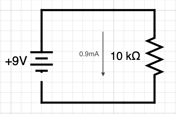
For a 6V battery, used with a 30kΩ resistor, the current flowing would be 6V / 30,000Ω = 0.0002 so 0.2mA.
Kirchhoff's Voltage Law
To figure out the voltage at different places in a circuit, we can use Kirchhoff's Voltage Law that states that the sum of the voltage differences around a closed circuit is 0.
If a battery supplies 9V to a circuit, all of the components in the circuit must collectively use the 9V, so, by the end of the loop, the amount of voltage going through the negative terminal of the battery will be 0v. Each component in a circuit uses some of the voltage provided, decreasing the electric potential.
Let's take the example below:
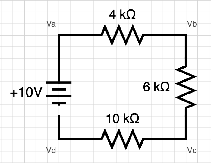
Between the battery and the 4kΩ resistor will be Va. Between the 4kΩ and 6kΩ resistors will be Vb. Between the 6kΩ and 10kΩ resistors will be Vc, and finally, between the 10kΩ resistor and the battery will be Vd.
In this circuit, the total resistance will be 4kΩ + 6kΩ + 10kΩ = 20kΩ, so the current going through the circuit will be 10V / 20kΩ = 0.0005 or 0.5mA.
Then, what is the voltage at each point relative to the negative terminal of the power supply?
Va is directly connected to the positive terminal of the battery so Va = 10V. After going through the first 4kΩ resistor, there will be a voltage drop and as we determined that the current going through the circuit is 0.5mA, the voltage drop will be 0.5mA * 4kΩ (0.0005 * 4000) = 2V. Therefore, Vb will be equal to 10V - 2V = 8V.
The same happens for the rest of the circuit. After going through the 6kΩ resistor, the voltage drop will be equal to 0.5mA * 6kΩ = 3V, so Vc will be equal to 8V - 3V = 5V.
Finally, after going through the 10kΩ resistor, the voltage drop will be 0.5mA * 10kΩ = 5V, so Vd = 5V - 5V = 0. This makes sense because Vd is directly connected to the negative terminal of the battery.
LED circuit
Let's try to implement this using a basic LED circuit.
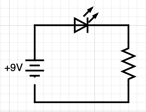
LEDs have a forward voltage of about 2V. Forward voltage means the amount of voltage used by the LED so as the current flows through the LED, it will use 2V.
Let's call the voltage of the LED Vf and the voltage of the resistor Vr.
9V = Vf + VrThis way, Vr = 9V - 2V = 7V.
Additionally, if we look at the datasheet of a LED, the current shown in the test conditions is 20mA, so to determine the resistance of the resistor, we can use Ohm's Law. As I = V / R, R = V / I.
So the resistance is equal to 7V / 20mA = 350Ω.
If we replace the power supply with a 5V one, like when powering a circuit using an Arduino for example, this calculation becomes:
(5V - 2V) / 20mA = 150ΩWe can verify that this works by calculating the voltage differences the same way as we did it previously.
The voltage going into the LED will be 5V. The LED uses 2V so the voltage after the LED will be 3V. As the current flows through the 150Ω resistor, the voltage will be 20mA * 150Ω = 3V, so what is left is 3V - 3V = 0V.
However, when reading the Arduino tutorial for the blink example, I noticed that they recommend to use a 220Ω resistor.
As an LED can have a forward voltage between 1.85V and 2.5V, it is safer to use a resistor with a slightly higher value, and depending on the type of resistor used (10% or 20% tolerance), the values available are 180Ω or 220Ω.